Ceramic Resonator Bfo Circuit

Hobby Electronics Circuits Stable 455khz Bfo For Ssb Reception Shortwave Radio Electronics Circuit Circuit Simulator

Metal Detector Circuit Diagram Free Download Image Search Results Metal Detector Gold Detector Metal Detector Reviews

Metal Detector Electronics Circuits Hobby Metal Detector Garrett Metal Detectors Electronics Circuit
Bfo Circuit

Pin On Electronic

Pin On گنجیاب
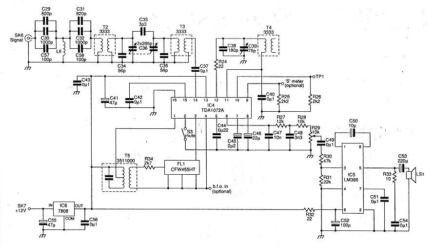
Because the ceramic resonator operates at fixed frequency no tuning of the circuit is required.
Ceramic resonator bfo circuit.

Pin On Electronics

Pin On Electronique

Roel Arits Electronics Hobby Shack Put Voltage Controlled Sawtooth Generator Eletronica

Create A Digital Volume Control Circuit Digital Circuit Circuit Diagram Electronics Circuit

455 Khz Signal Generator

Pin On Skema Radio

A Beat Frequency Oscillator

Cap Sistema Em 2020 Arduino Projeto De Automacao Residencial Diagrama De Circuito

Tl074 Opamp Google Zoeken Elektronnaya Shema

Pin On Electronics Projects

Voice Switch Circuit Diagram Related Posts To Sound Activated Switch Voice Switch Circuit Diagram Circuit Diagram Circuit The Voice

Pin On Life Changing Technology

Http Howtodosteps Blogspot Com Eg 2016 10 Simple Easy 37 Volts Dc To 3000 Volts Html Simple Easy How To Make Homemade

Simple Bfo Metal Detector Schematic Diagram

H Bridge Microchip Pic Microcontroller Pwm Motor Controller Ermicroblog Pic Microcontroller Microcontrollers Learn Robotics
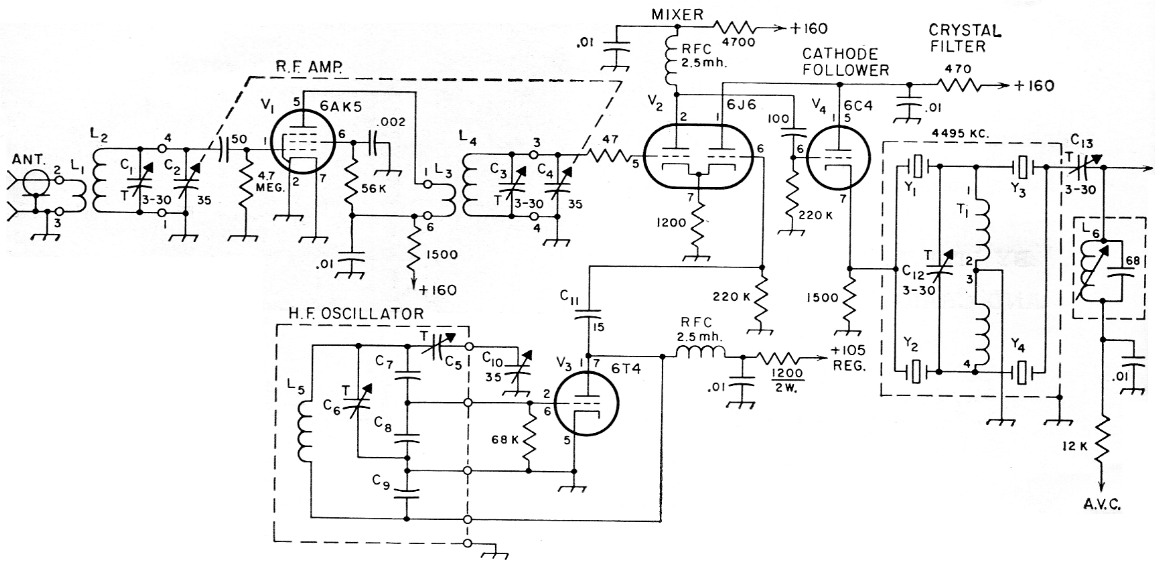
Some New Ideas In A Ham Band Receiver

Receiver And Receiver Accessory Circuits
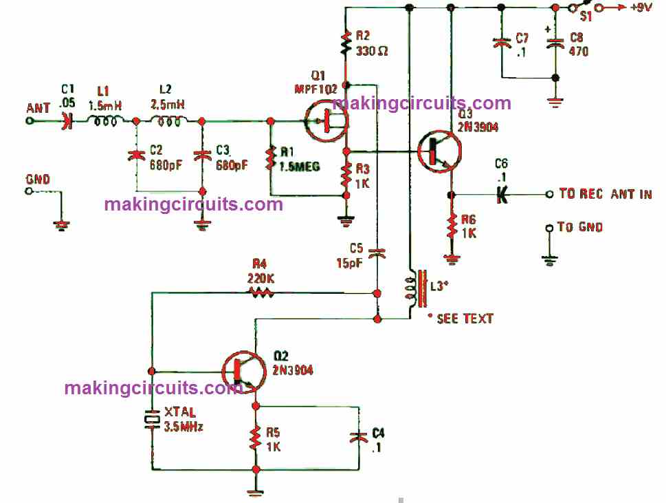
Very Low Frequency Vlf Converter Circuit
3
Source : pinterest.com
